Building a Drivetrain
Building your drive is the next step in the process; hopefully you picked a drive speed, gearing, and everything else from the Drivetrain Design entry. Now we will cover building your drive.
Chassis
I'll call the chassis the drive layout without any wheels and gearing on it. In this part, you will get your C-channels for the drive, mount the cross braces, and put on your bearings. You will need at least 6 pieces of metal, the drive channels, and the cross braces to build the frame.
Drive Channels
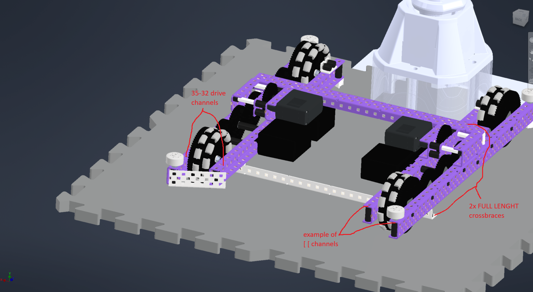
- Drive channels: the parallel metal on your drive chassis everything is mounted on. There are different layouts; they include: (note:
[ [,] [,[ ]is the common way to represent C-channel direction on a drive)[ [: this is my favorite; it mounts the motors inwards and looks the nicest] [: this mounts motors inwards and is easy to work on at the cost of around .062" of less space compared to[ [; 2nd favorite, but I don't run it[ ]: I've seen newer teams run this; I don't like this. It mounts the motors super far out and is still hard to work on. Do not recommend.
Bearings
Mounting bearings: Lay out your gear chain and determine the location of the bearings; these pieces of plastic reduce friction and decrease gear slop and are NEEDED on the drive. Of the different bearing types, I recommend v3 ones because they only need 1 screw. Also use nylon/aluminum screws to save weight.
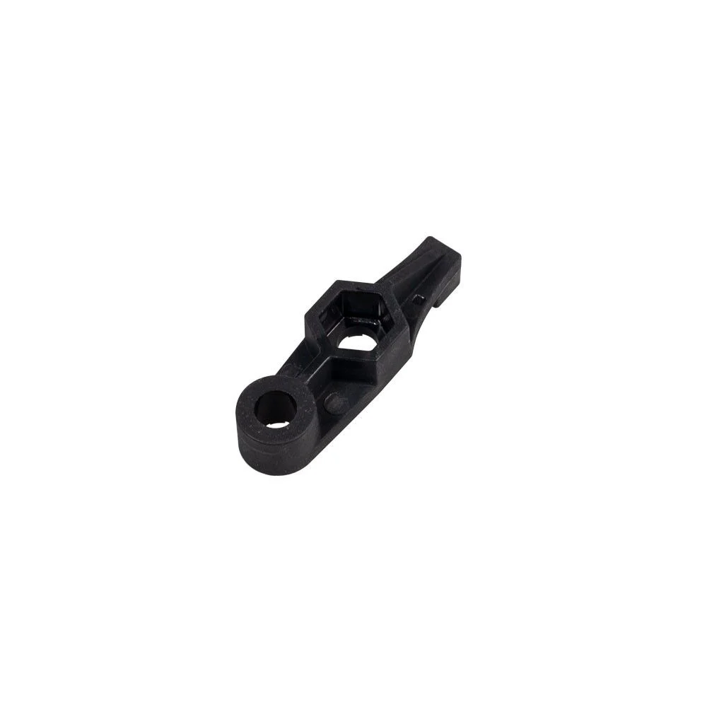
A V3 bearing.
Drive base bearings (V3 bearings).
Cross Braces
- Cross braces: perpendicular metal covering side to side of the drive; I recommend at least 2 of them.
Mounting your cross braces: You can mount your cross braces with either standoffs and 2 screws or lock nuts and spacers with a nut and screw. Standoffs are by far easier to take off but you have to Loctite one side for the screws to not come loose. Lock nuts and spacers are more secure but are a PAIN to take off requiring a lot more skill and effort. (personally I use standoffs).
Other
Squaring your drive: Your drive needs to be perfectly parallel and perpendicular. In order to achieve this, copy this video:
I also recommend using shoulder screws for a more precise fit.
Boxing your drive: Use .875" spacers on the corners of your drive.
Drive Chain and Wheels
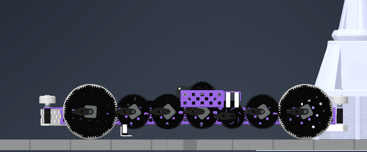
The next step is adding your gears wheels and motors. First, let's add the drive gears and idlers.
Drive Gears
Drive gears: these are powered gears and will be mounted on a shaft. I will leave spacing up to you to decide but I'll go ahead and warn you: you need the gears to have around 0.062” of clearance from the drive channels.
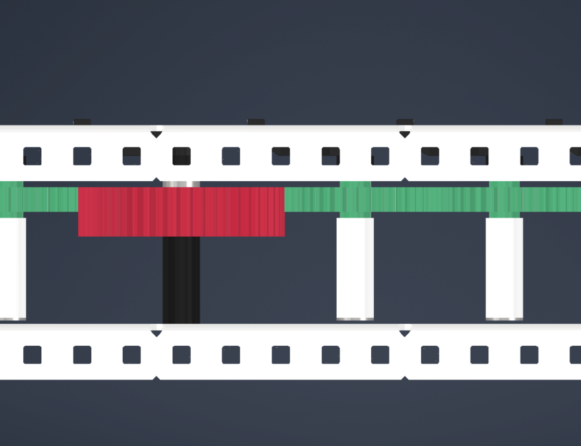
Drive gears (green) and an idler gear (red). Notice the gap from the side of the drive.
Wheels
Mount the wheels last. The wheels will be on screw joints using 2.5" screws. The gears/wheels need circle inserts. I space the gears .031" off the wheel. Make sure to use 2 screws and nylon lock nuts to secure the wheels to the gear. I mount the wheels/gear assembly at least .62" off the channel.
Screws: I recommend flat head screws on your wheels to increase clearance. You can either purchase them or use a sander to make them.
Motors
This is fairly simple; all you need to do is screw the motors where your drive gears are. Do NOT use bearings on motors; this mounts them further out and increases friction. Motors are bearings themselves, so do not do this.
By Harrison Elkins